Introduction to Decision Model and Notation (DMN)

In this blog, we share an introduction to Decision Model and Notation (DMN), looking at the various components of a DMN model, including Decision Requirements Diagrams (DRD), Custom Data Types and FEEL expressions.
Written by John Cornforth, Head of Professional Services
What is DMN?
Decision Model and Notation (DMN) is the industry standard for business decision modelling using diagrams as opposed to code. It is a vendor-neutral standard maintained by the Object Management Group (OMG), the same organisation behind Business Process Model and Notation (BPMN). In BPMN, a business process is designed as a “workflow” diagram. You can think of DMN as the business rules equivalent of that: in the same way, DMN allows you to model the structure and logic of a business rule graphically, as opposed to having to code everything in Drools Rules Language (DRL).
The business rules, or DMN models, can be written using a variety of tools, and can be deployed and executed either as part of an existing application, or as discrete decision services either on traditional server platforms or as serverless containers. You can also embed your DMN models within a BPMN business process using the traditional BPMN decision task.
A DMN model consists of a number of components that make the model work, including at least one Decision Requirements Diagram (DRD), a set of Data Types that you can define, and expressions written in the FEEL expression language to define the logic. We will look at each of these in the next sections.
DRDs
A DRD is a visual representation of your DMN model, kind of like a decision tree. You add Decision Nodes, Input Data Nodes, Business Knowledge Models and other components to your canvas, and connect them up in a way that makes logical sense when viewing the diagram. Here’s an illustration of a simple DRD, in this case a fairly simple example to work out a price based on factors like the customer’s age and a membership discount:
Now let’s look at some of the individual elements of the DRD:
Input Data Nodes
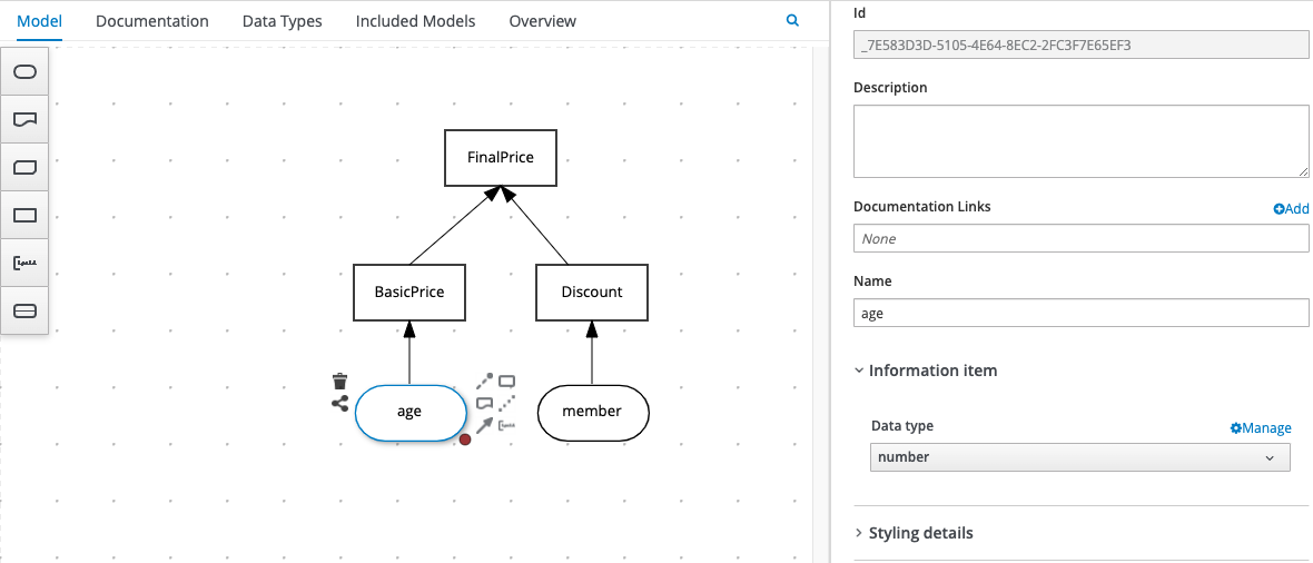
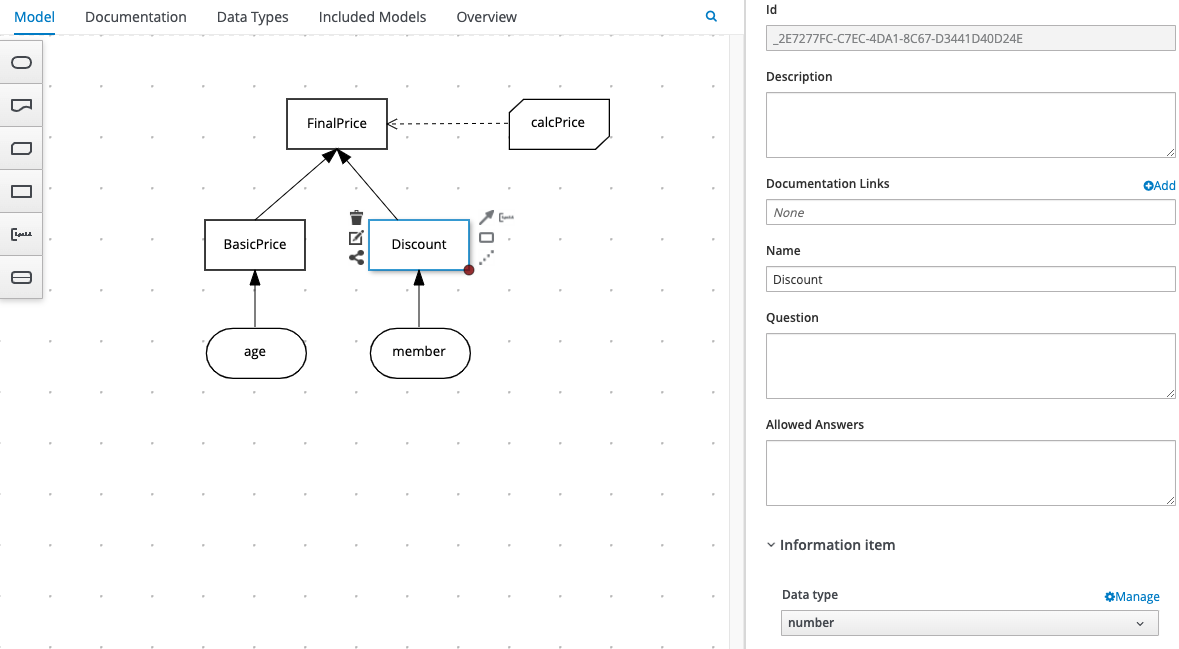
Input Data Nodes, represented as boxes with rounded corners on the diagram, are the input data on which we’ll perform some decision logic. They are variables that will be provided at execution time, so in our model we give them a name and a data type, but don’t provide the actual data itself. In our example, we have 2 Input Data Nodes, representing the 2 pieces of data we need to make our decisions i.e. “age” and “member”. In this illustration you can see how we configure an Input Data Node using the DMN editor’s properties sheet:
We can now refer to the names of the Input Data Nodes in our Decision Nodes, which we’ll look at next.
Decision Nodes
Decision Nodes are where you put your logic and are represented as boxes with straight edges on the diagram. In our example, we have 3 Decision Nodes: one for calculating a BasicPrice based on the customer’s age; another for calculating any membership Discount available; and a final decision which takes the results of the previous 2 decisions to calculate a FinalPrice.
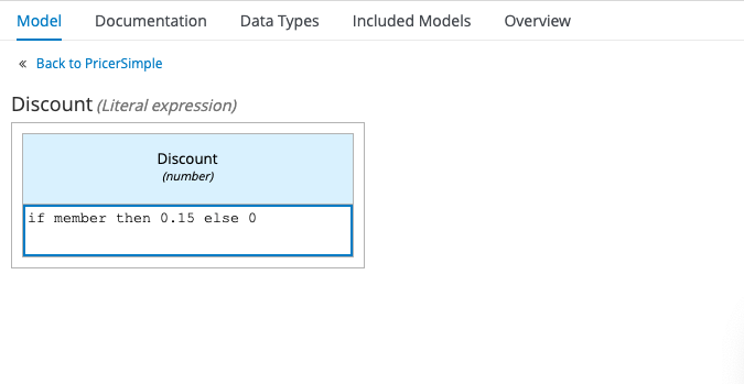
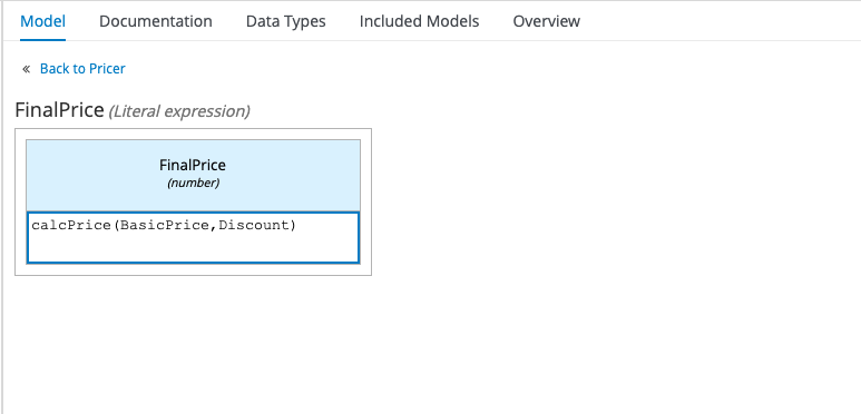
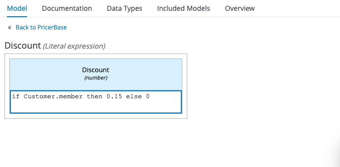
The way that you construct your logic can be as simple or as complex as you like, ranging from a single Literal Expression in the case of our Discount example:
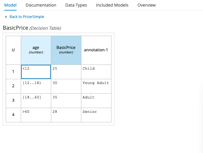
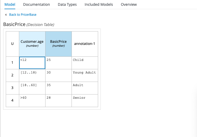
to a Decision Table, in the case of our BasicPrice example:
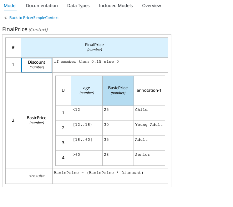
or even a Context – a combination of any of the above (referred to as “boxed expressions”) that resolves to a single result, like this:
Now you can get pretty creative with these, even going as far as nesting Contexts inside Contexts(!), but bear in mind the whole point of a DRD, and of DMN in general, is to give business people a means of representing decision logic graphically. It strikes me that embedding a whole bunch of complicated logic into a single Decision Node is not the best way to achieve that. Personally, I try to keep my Decision Nodes relatively simple and use lots of them, rather than embedding a lot of logic in a single node. However, that’s just my preference, and it does tend to make for busier diagrams!
Business Knowledge Models
Another useful component of a DRD is a Business Knowledge Model (BKM), represented as a box with diagonal corners. BKMs are reusable functions that you can apply to decisions where the logic is the same, but the input data are different.
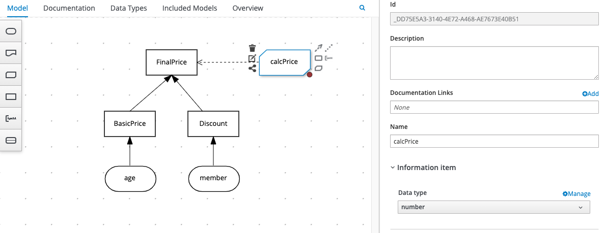
In the following example, the logic we used in the FinalPrice decision has been moved out into a Business Knowledge Model called calcPrice, as illustrated here:
As this is an abstracted function, we first need to define its parameters, as follows:
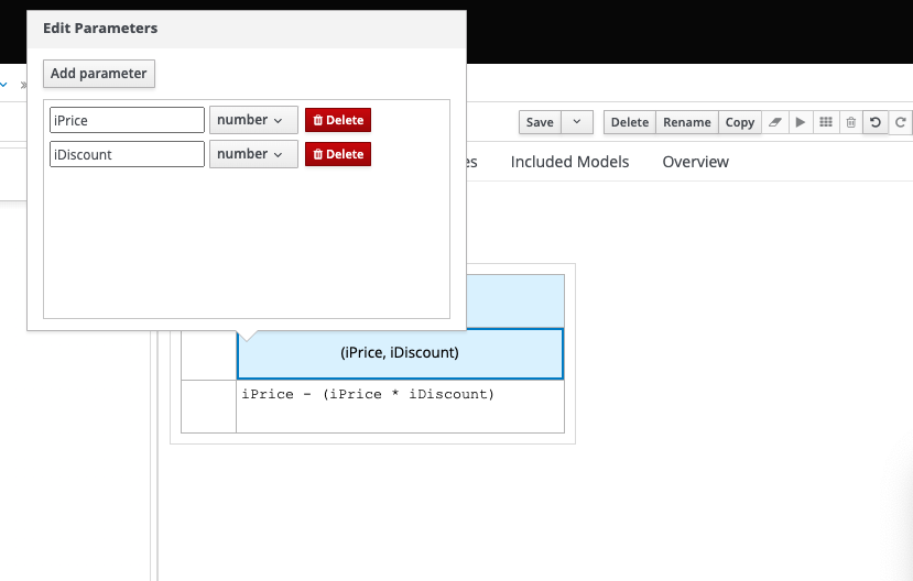
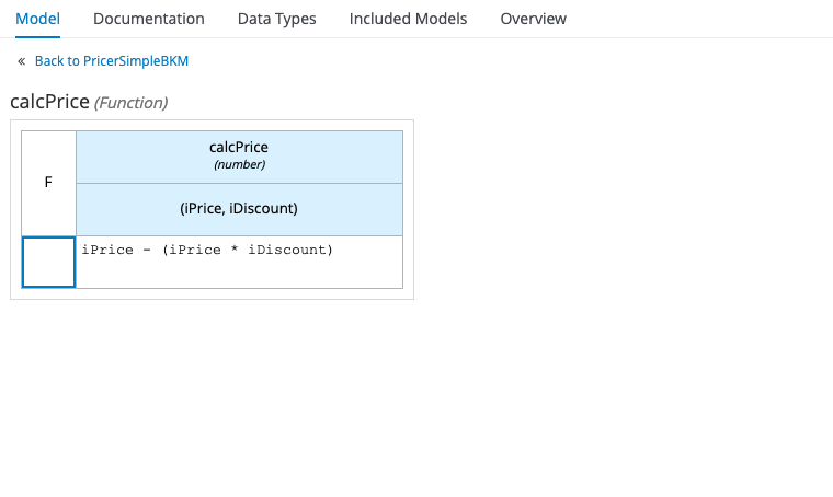
We can then use those parameters in our expression, as follows:
Finally, we can replace the expression in our FinalPrice Decision Node with a call to the calcPrice Business Knowledge Model, passing in the results of the other two Decision Nodes as parameters:
Strictly speaking, we don’t need a reusable function in our example, as we’re only running that calculation once, but hopefully you can see the potential of Business Knowledge Models.
Data Types
In order for your DRDs to function effectively, there is a key attribute that you should configure for all of the DRD elements we’ve mentioned above, including Input Data Nodes, Decision Nodes and Business Knowledge Models: that is the data type that your node will return – so is it simply a true / false evaluation, a number based on a calculation, or a value looked up from a Decision Table? In some cases, you might want the value returned from one decision to be used as input for another, so it’s important to define its data type. Here’s a reminder of how we configure a Decision Node’s data type using the DMN editor’s properties sheet:
When we specify a data type for Input Data and Decision Nodes, we can use the standard data types that you’re probably already familiar with (boolean, number, string, date etc.) but a DMN model also allows us to define our own, including complex, multi-field data structures. This is really useful as it allows us to talk in terms of real-world business data when defining our decisions, such as “customer”, “vehicle” or “loan”.
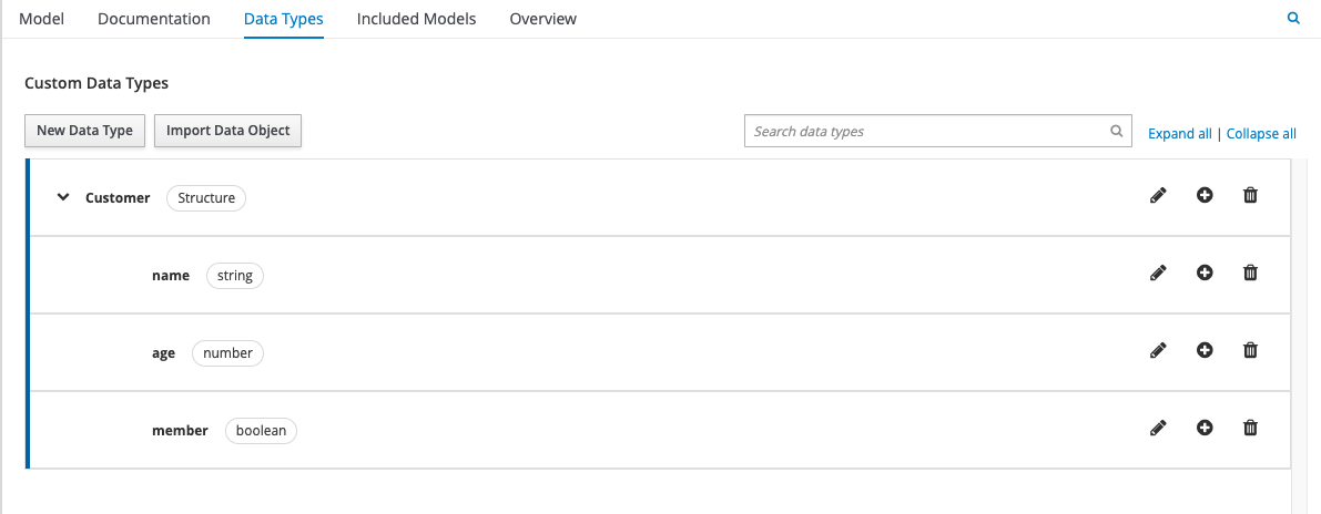
The Data Types section of your DMN editor allows you to define those custom data types. If you choose a Structure as your custom data type, you are essentially defining an object that has attributes, each of which have their own data type, as illustrated below:
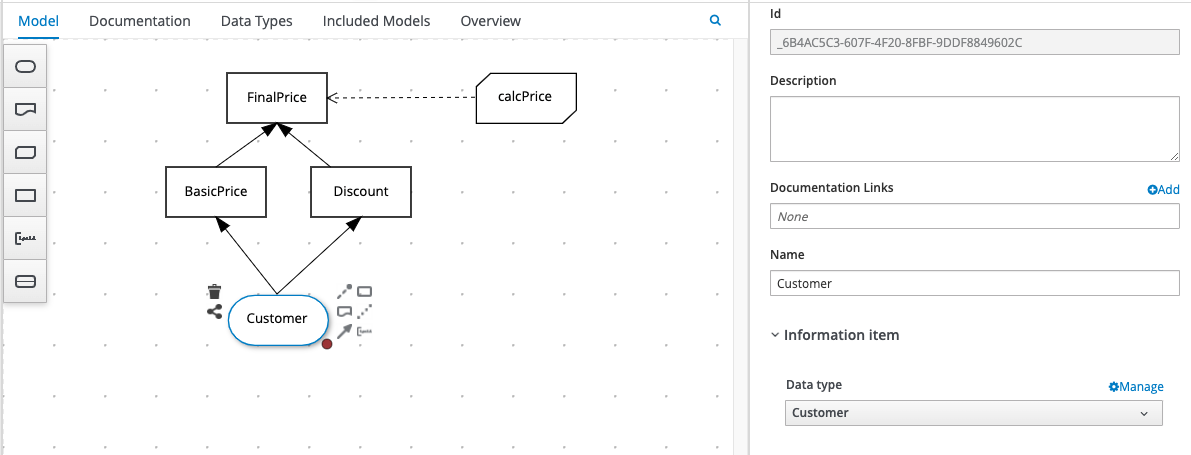
In our example, we’ll replace the individual Input Data Nodes for “age” and “member” with the complex object type, “Customer”, illustrated above. This is what the new DRD will look like:
The corresponding Decision Nodes will also change, as we are no longer referencing simple Input Data Nodes “age” and “customer”: instead, we’re referencing a single Input Data Node, “Customer”, that has attributes. We do that using a simple dot notation as follows:
Customer.age
Customer.member
This is what the resulting Decision Nodes will look like:
You can take this concept to extremes by having custom data types that have attributes that are other custom data types, and in this way you start to create an object hierarchy. Just be careful of going too far with this, particularly with Input Data Nodes, as the code that calls your decision services may have to pass quite a complex data structure in order for it to work. But for those applications that already work with a complex object model, DMN is great because you can effectively match that model in your decision services. If you’ve written that object model in Java, some tools will even let you import that model straight into the DMN editor!
FEEL Expressions
FEEL stands for Friendly Enough Expression Language, which is the language we use to write the expressions that make up the decision logic within our DMN models. FEEL supports all the basic data types mentioned above, including a few extra useful ones such as day / time and year / month durations, ranges of values, and lists. FEEL also supports all the common comparative operators such as = > < etc. plus expressions such as if, for and in. It also has a bunch of handy built-in functions for manipulating strings, lists, numbers, dates and times.
In our example, we’re using a simple FEEL if statement for the Discount expression, but we’re using FEEL ranges (also called “intervals”) in our BasicPrice decision table. One thing to watch out for with intervals is the brackets that you use, which determine whether your range’s start and end are “open” or “closed”:
round brackets ( or ) denote “open” start or end
square brackets [ or ] denote “closed” start or end
An “open” start or end includes anything within the interval’s boundary, but not the boundary itself, in other words (12..18) incudes every number between 12 and 18, but not 12 or 18 themselves. In the following example, the starts and ends of all the intervals are “open”, resulting in gaps in logic:
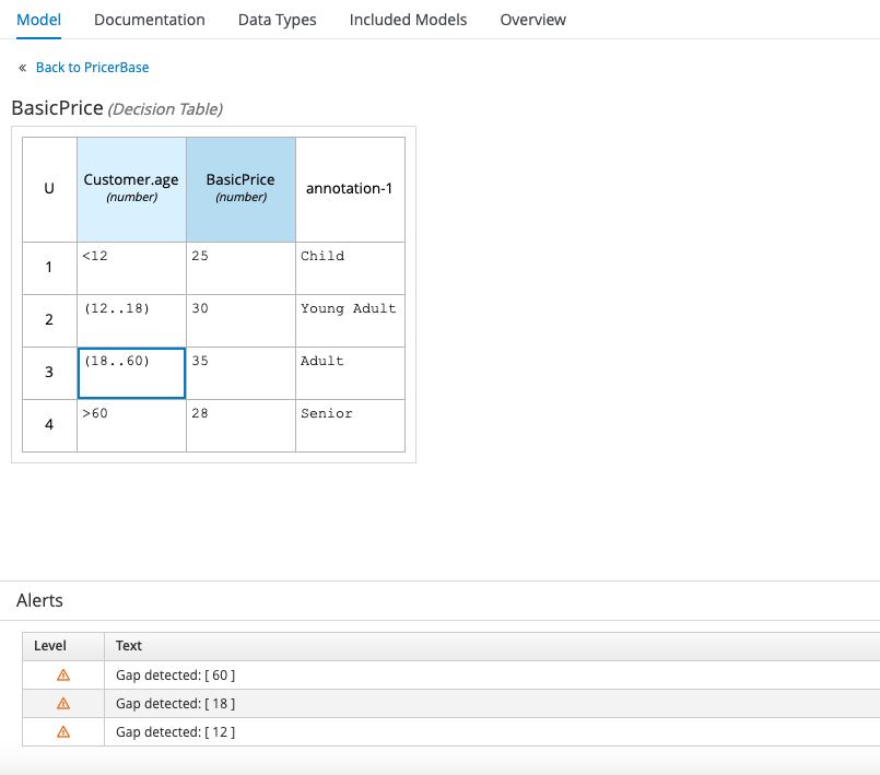
If the customer’s age is exactly 12, 18, or 60, these cases aren’t catered for and the decision table doesn’t work. The correct way to express these intervals is by using closed starts for each of the intervals, and a closed end for the second interval to include 60, as follows:
Once you get familiar with the basic syntax, FEEL is reasonably easy to pick up. I’d recommend keeping the DMN handbook handy for your first few expressions though (link provided at the end of this post).
Also look out for a new dialect of FEEL, called B-FEEL (“Business-Friendly Expression Language”) which has been introduced as part of DMN 1.6. This is in response to criticism that FEEL is not quite as business-friendly as originally hoped, and attempts to deal with issues such as how FEEL handles null values.
Testing DMN Models
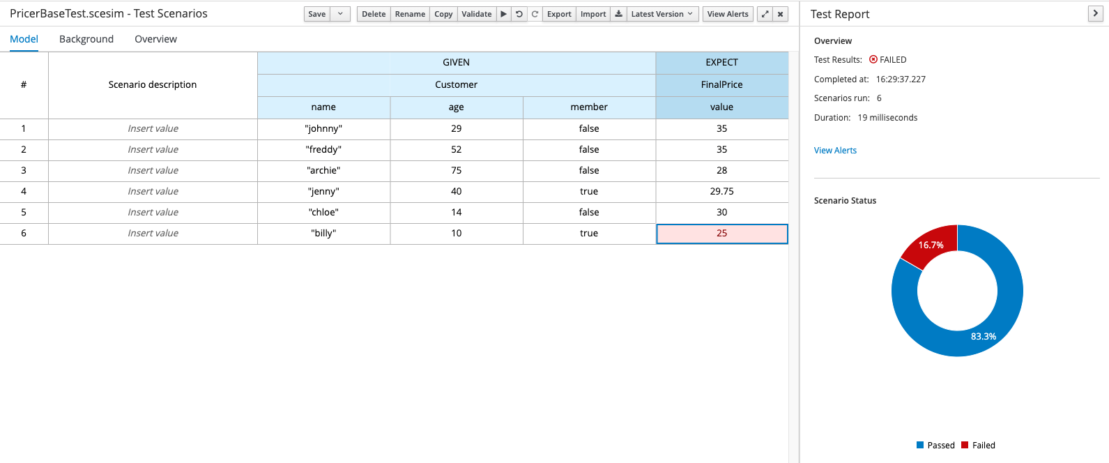
There are a number of ways to test your DMN models, and a lot will depend on what tooling you’re using. If you’re using any of the open-source tools such as Red Hat Decision Manager, IBM BAMOE or the associated Visual Studio plugins, you will have a Test Scenario Editor that you can use to create SCESIM (Scenario Simulation) files. These files are basically tables, each row of which contains a scenario (sample input data) and an expected result. When the tests are run, each scenario is evaluated and given a “pass” or “fail” based on whether or not the expected value is returned. Here’s an example:
Construction of Test Scenario files is not strictly part of the DMN specification and as such is outside the scope of this post, but you can find more information via the link at the end of this post.
You can also see your DMN in action by deploying a decision service and running it. Again, this will depend greatly on the type of project you have and the deployment platform you’re using, but assuming you are deploying your decision services as REST endpoints, the input and output should be pretty standard.
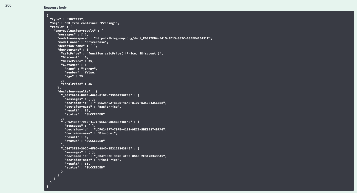
Here’s an example of how to execute a decision service via REST using the Swagger documentation provided by the KIE execution server included in the Red Hat Decision Manager / IBM BAMOE products:
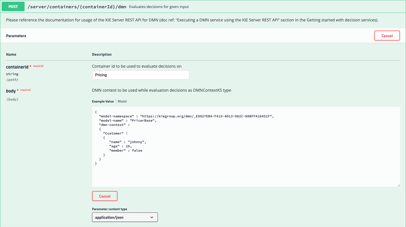
And here is the result:

As you can see, there is quite a lot of output – including the evaluation of every Decision Node – but you should see the resultant price calculated correctly. Some of this output may be considered unnecessary, and in the next blog post we’ll be showing you how to cut this down to just the relevant info.
Summary
In this post we’ve had an introduction to DMN, looking at the various components of a DMN model, including Decision Requirements Diagrams (DRD), Custom Data Types and FEEL expressions. In the next post, we’ll be expanding on that knowledge in order to create re-usable Decision Services.
If you found this article helpful, why not explore more of our Technical Blogs written by our experts.
Further Reading
For general information on DMN, and to download the specification, see the Object Management Group’s website here.
For best practice on all things DMN and BPMN, see Bruce Silver’s website Method & Style here.
For a more in-depth introduction to DMN see Bruce Silver’s blog here.
For a detailed FEEL reference see the DMN FEEL handbook here.
For more information on creating Test Scenarios see the KIE blog here.